
Hot Tip #25 - Unit of thermodynamic energy
The British thermal unit (BTU or Btu) is a unit of energy equal to about 1.06 kilojoules.
It is the amount of energy needed to heat one pound of water one degree Fahrenheit.
Engineers use MMBTU to represent one million (106) BTUs.
A Therm is used to represent 100,000 (105) BTUs.
Examples:
One boiler horsepower is equal to 33,479 BTUs per hour.
One cubic foot of natural gas is about equal to 980 BTUs.
A 400-pound dryer will have a maximum burner rating of about 25 Therms per hour.
A gallon of diesel fuel has about 138,700 BTUs per US gallon.
A gallon of regular gasoline has about 125,000 BTUs per US gallon.
To heat a small (10,000 gallon) swimming pool from 58 F. to 78 F. requires:
10,000 gallons * 8.34 pounds/gallon * 20 degrees = 1,668,000 BTU’s
Hot Tip #24 - Stain Gauge
How does the strain gauge on my tunnel loading conveyor work?
The strain gauge is one of the most widely used strain measurement sensors. It is a resistive elastic unit whose change in resistance is a function of applied strain.

Where R is the resistance, e is the strain, and S is the strain sensitivity factor of the gage material (gage factor in some books).
Among strain gages, an electric resistance wire strain gage has the advantages of lower cost and being an established product. Thus it is the most commonly used type of device. Other types of strain gages are acoustic, capacitive, inductive, mechanical, optical, piezo-resistive, and semi-conductive.
A wire strain gage is made by a resistor, usually in metal foil form, bonded on an elastic backing. Its principle is based on the fact that the resistance of a wire increases with increasing strain and decreases with decreasing strain, as first reported by Lord Kelvin in 1856.
When the strain gage is attached and bonded well to the surface of an object, the two are considered to deform together. The strain of the strain gage wire along the longitudinal direction is the same as the strain on the surface in the same direction.
Hot Tip #23 - Salt Usage
Are you using too much salt when you regenerate your softeners?
Most laundries are.
A simple check: Salt usage should be between:
3.1 to 3.6 grains of salt used per grains of hardness removed.
I round it off to between 3 & 4 grains per grain.
Another way to state that is, that one pound of salt usage should remove between:
1,950 grains of hardness, when regenerating at 15 Lbs of salt per Cu.Ft. of resin and
2,450 grains of hardness, when regenerating at 12 Lbs of salt per Cu.Ft. of resin.
A gallon of brine will have:
Percent saturation pounds of salt per gallon of brine
95% = 2.491
96% = 2.522
97% = 2.552
98% = 2.570
99% = 2.616
100% = 2.647
Therefore, if you regenerating at 12 pounds of salt per cubic foot of resin and have
25 cubic feet of resin, your brine usage should be
(25 Cu.ft.*12 lbs./cu.ft.) = 300 pounds of salt
(300 Lbs / 2.491 lbs/gallon) = 120.4 gallons of 95% saturated brine needed.
Brine usage should be measured at every regeneration!
If your city water hardness is 10 grains, then you should be regenerating every:
(27,000 grains/cu.ft. at (12 Lbs) * 25 cu.ft / 10 grains/gallon) = 67,500 gallons = 2,450 grains per pound
(29,200 grains/cu.ft. at (15 Lbs) * 25 cu.ft / 10 grains/gallon) = 73,000 gallons = 1,946 grains per pound
Brine usage should be measured at every regeneration!
Did I already state that brine usage should be measured at every regeneration? It is the best methodology to confirm that regeneration was performed correctly. Which salt dosage should you regenerate at? That’s a future Hot Tip!
Hot Tip #22 - Boiler Blowdown Exchanger
Boiler blow-down occurs from two different boiler locations. The first location is from the bottom of the boiler water reservoir.
This is known as “bottom blow-down” or “rapid blow-down”. It is usually less than 10 seconds in duration and depending on water quality is performed once or twice per shift.
This blow-down is intended to remove “mud” from the bottom of the boiler. The high velocity and short duration of this blow-down do not make it a good candidate for heat recovery.
The second location is from the top of the boiler water reservoir. This is known as “top blow-down”, “surface blow-down” or “continuous blow-down”.
This method of blow-own is continuous in duration and the volume of blow-down depends on water quality; as determined by boiler water chemical analysis.
This method of blow-down is intended to remove contaminates that are floating on the boiler water surface. The majority of all boiler blow-down water is from this “Surface blow down” method.
I measured a heat exchanger on a 400-horse power boiler that was heating water, which had a flow rate of 2.4 GPM, 90 degrees.
This boiler had fairly clean make-up water and blow-down seemed to be in good control.
At $8.00/MM Btu and 80% thermodynamic efficiency, this exchanger was recovering $1.04 per hour.
At 4,000 run hours per year, the total savings would be = $4,323 per year.
Calculations:
2.4 GPM * 60 Minutes/Hour * 8.34 pounds/Gallon * 90 degree rise * 4,000 Hours/Year * 4,000 Hours/Year * $8.00/MM Btu / 1,000,000 / 80% efficiency = $4,323/Year.
Note: If an exchanger is to be installed, comply with all safety codes! You do not want to install this wrong!
Hot Tip #21 - Refrigerant Type Compressed Air Dryers
Question: I have a refrigerant air dryer after my compressor. The temperature of the exit air is only “slightly” colder than the inlet air, and yet the dryer seems to be working fine. How is this possible?
Within the compressed air dryer, there are two heat exchangers.
Exchanger # 1 is a compressed air to compressed air heat exchanger.
Exchanger # 2 is a compressed air to refrigerant heat exchanger.
The path of the compressed air flow is:
First, it enters side A of exchanger # 1, exits exchanger # 1, then enters side A of exchanger #2, exits exchanger # 2,
then enters side B of exchanger # 1, then exits exchanger # 1 and exits the dryer.
Approximate temperatures of the heat cycle are:
Entering # 1 A (100 F) Entering # 2 A (60 F)
Entering # 1 B (40 F) Exiting # 1 B (95 F)
When the compressed air exits exchanger # 2 its temperature has been reduced to below the dew point.
At this point, the water drops out and exits the dryer via the water separation trap.
The dry, cold compressed air then enters side B of exchanger # 1 where it absorbs heat energy from the air on side A.
It now exits the dryer at a temperature “slightly” cooler than the entering air.
Hot Tip #20 - Ozone
Instead of adding ozone, it is much cheaper & safer to use a low-pressure high-volume blower to blow atmospheric air into your wash water. The addition of this air seems to have all of the same benefits as the ozone. I do not know if the benefits are due to:
- The oxygen & ozone that is in the ambient air
- The increase in mechanical action caused by the injection
- Or if the injection is causing the wash liquor to become more homogeneous.
I know that you will not get as much ozone into the washer but the increase in O2, a great oxidizer by itself, maybe the cause of wash quality improvement.
A simple calculation comparing the amount of oxygen plus ozone present in your ambient air to the amount of ozone generated by the ozone generator will determine the size of the blower needed.
Facts:
- There are about 5 grams of O2 in a cubic foot of air.
- Ozone generators are available in many sizes with 30 grams per hour a common size.
- Ambient ozone is frequently in excess of 100 PPB.
- Blower output pressure will need to be about 2 PSIG = 4.6 feet of the water column.
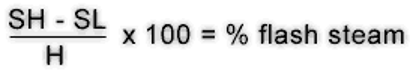
Hot Tip #19 - Flash Steam
The percentage of flash steam (by weight) that will be formed when discharging hot condensate to a lower pressure is easily determined by using this formula. The sensible heat (heat of the saturated liquid) of the condensate at the lower pressure is subtracted from the sensible heat at the higher pressure. This number is then divided by the latent heat of the steam at the lower pressure and multiplied by 100 to get a percentage.
| SH | = | Sensible heat in the condensate at higher pressure before discharge |
| SL | = | Sensible heat in the condensate at the lower pressure to which discharge takes place |
| H | = | Latent heat in the steam at the lower pressure to which the condensate has been discharged |
Example:
If 100psig hot condensate is discharged to atmospheric pressure, the percentage of flash steam is determined as follows. (It may be helpful to have a copy of the steam tables available for reference.)
Subtract the sensible heat of the condensate at the lower pressure (180 Btu/lb) from the sensible heat of the condensate at the higher pressure (308.8 Btu/lb) and the answer is 128.8 Btu/lb. This figure is divided by the latent heat at the lower pressure (970.3) to yield .133 which, when multiplied by 100, provides an answer of 13.3 percent.

Bonus Hot Tip!
When fly fishing a Montana spring creek, that you have hiked into, remember to drink upstream from the herd
Hot Tip #18 - One More Degree
Frequently when I’m talking to laundry operators or their engineers, I ask them what it would be worth to them if they could recover one more degree with their wastewater heat recovery system. The most common response is “Gee, I don’t know”. When encouraged to make a guess, their response is something like “I bet it’s a lot, maybe several hundred dollars a year”.
Since effort will be needed to recover this one more degree, I think it is important to calculate its’ value, to justify the recovery effort.
The calculation is:
(Pounds of water discharged down the drain yearly) Divided by (1,000,000) Multiplied by
(fuel cost, per 1,000,000 BTU’s) Divided by (overall thermodynamic efficiency)
Note:
- Water discharged is about 3% less than water purchased.
- Multiply gallons by 8.34 to get pounds.
- If you do not know your overall thermodynamic efficiency and you think you are doing a really good job at controlling fuel usage, use 80%. (read chapter 12 of TRSA’s Textile laundering Handbook)
Example:
(30,000,000 gallons per year) X (8.34#/gal) / (1,000,000) X ($11.00 MM BTU) / (80% Eff.) =
$3,440.25 per year. This number will be higher if you are not doing a real good job at controlling fuel usage.
As you can see, there is ample justification to expend effort to recover one more degree.
How many degrees are available for recovery?
If your discharge temperature is constantly within 10 degrees Fahrenheit of your incoming water temperature, you are doing very well! Many plants have reached this level. The best I have seen is a six-degree “cold end approach”. That plant had 60 F incoming water with a 66 F effluent temperature. It becomes easier as your incoming water temperature increases.
Hot Tip #17 - Ironer Folder Drops
Like most problems in life, the cure will be obvious once we know the cause. Since we have the problem we can further deduce that the cause is not obvious; therefore let’s look at some not-so-obvious possible causes. Is the problem sporadic? The answer is obviously yes; otherwise, every item would be dropping. There are three “systems” incorporated in folders that could cause sporadic problems:
Mechanical, Electrical & Pneumatic.
Of these three, the least obvious cause is the Pneumatic systems. Check your air pressure. Install a large, four-inch, or larger, diameter pressure gauge at the folder. Watch the pressure closely; are there drops in pressure while the folder is off? If so, what is causing the drop? Look for the non-obvious possible causes. If the drop in pressure is slow to recover, we know two things: 1) the cause uses a lot of air. 2) The cause is for a long duration.
Areas to check:
A) Compressor capacity, is your compressor performing to its rating?
B) Air blow-down by maintenance or custodial departments.
C) Large air-driven pumps or motors, are frequently found in wastewater treatment systems.
If the drop in pressure quickly recovers we know two things: 1) The cause uses a lot of air. 2) The cause is for a short duration.
Areas to check:
A) Large diameter air cylinders, frequently found in rail lifts.
B) Solenoids installed on airlines for automatic blow-down; lint collectors are a good example. If you find this to be the problem, reduce the pipe size after the solenoid to ¼” soft copper and pinch the copper closed until it takes more than 3 minutes to fill the air receiver tank on the dryer. Air will not be needed until the next blow-down cycle, 15 minutes or more after the first cycle. Remember, if it was easy it would have been obvious and anyone could have solved it!
Hot Tip #16 - Air Leaks
While visiting laundries one issue frequently arises, how to handle compressed air leaks.
Most leaks that I find are very difficult to correct. The easy ones are generally corrected by facility maintenance long before I arrive. The easy ones are those that you find in the air delivery plumbing. Examples include: leaking quick disconnects, a pinhole in plastic airlines, leaks at pipe threads, etc.
Difficult leaks to correct are those internal to the air components such as: Air motors on chemical mixing tanks, air cylinders leaking through the piston or shaft packing, control valves blowing out the exhaust ports, etc. Many laundries have in excess of 50% of their total compressed air lost through leaks!
I was recently in a plant where a six-inch diameter, eight-foot stroke; air cylinder soil lift had a major leak. This horizontal cylinder was 18 feet above the floor, placed between the roof rafters. Maintenance stated that it would require four hours to disassemble and repair the cylinder. I was informed that the plant was running 20 hours per day, 7 days a week. There was “no way” to repair this major leak! So it remained to leak for years! This was a difficult leak to correct!
Amazingly, once it was determined that the soil lift leak was the cause of many of their ironer folder problems, a way was found to get it fixed within three days. It was later calculated that the leak had been consuming $120.00 per week worth of electricity.
Hot Tip of the week; install a solenoid valve on each piece of equipment that uses compressed air; folders, ironers, dryers, etc. This should be a three-way valve so that when de-energized it bleeds the machine of all stored pressure. Now your leaks will only occur while that specific machine is running.